OS RAM Technical
Introduction
The OS RAM module provides two 15KB shadow RAM banks in the BBC's operating system address space. This extra RAM can be used for data or code. In normal data mode the memory is invisible to the operating system so OS calls or interrupts work normally.
This page explains the hardware and describes how to use the modules.
Link to BASIC software examples
Link to advanced software example
Hardware description
The module fits in the Operating System ROM socket (IC 51) on a BBC Model B. The OS ROM is then inserted into the piggy back socket on the top of the module.
The module has 32kB of RAM on board which is split into two banks A & B. There is a programmable logic device (PLD) which controls the access to the OS ROM, RAM and has the registers which set the operating mode.
Memory Map
The RAM on the module appears in the same address space as the OS ROM from &C000-&FBFF. The 3 pages of I/O (Fred, Jim and Shiela) are always accessible regardless of module register settings.
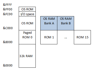
User RAM
The user RAM banks A & B are accessible from any program or paged ROM running in the machine including BASIC.
The top 1KB of memory (4 pages) is reserved for the memory mapped IO and OS ROM leaving 15KB of user memory available in each bank.
IO space
The BBC Micro memory mapped IO (pages &FC, &FD and &FE) is selected at all times. RAM cannot be paged in at these locations.
PAGE &FF
Reads from the top page of memory will always see the OS ROM (unless in RAM only mode). Writes to the top page will be directed to the module control register.
The top page RAM is only accessible when machine code is running from OS RAM in RAM mode.
Operating Modes
On power up the module defaults to ROM mode and bank A is selected for read and write. It will retain the most recent settings while the machine is powered up even across resets (BREAK) until the machine is powered off.
1. ROM mode
RAM on the module is disabled. The operating system ROM is always selected for full compatibility with a standard unexpanded BBC Micro. All bank selection commands are ignored in ROM mode.
2. ROM + RAM mode
The operating system runs normally from the OS ROM. Memory accesses by applications read and write from the RAM. Reads from the top page (&FF) will return OS ROM contents. NMI, IRQ and RESET vectors are pulled from the OS ROM.
3. RAM mode
The operating system is no longer available. User machine code may execute from RAM. NMI, IRQ and RESET vectors pull from RAM so should be initialised.
OS RAM Register
The OS RAM module has one 4 bit control register through which you set the operating mode and select RAM bank.
The module's control register is accessed by writing to any address in the top page (&FF) with an instruction executing from main memory or paged ROM (&0-&BFFF). This means sequential OS RAM commands can be issued from BASIC in one statement using the 4 byte ! operator.
The control register contents cannot be read. Do not perform read-modify-write instructions on the control register, this will result in undefined behaviour.
When in RAM only mode 6502 load/store instructions executing from the top 16KB of memory (&C000-&FFFF) will access RAM in the top page. Any instructions running in the lower 48K of the address space will access the control register in the top page in RAM mode. So any code which modifies the control register must execute from the lower 48K.
Mode control
The OS RAM module uses a state machine to select the current operating mode.
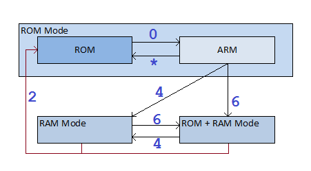
It is necessary to transition via ARM when leaving ROM mode in sequence. Any write when armed which is not a valid mode change command (including NOP) will revert back to ROM mode. It is recommended to first set ROM mode during application initialisation to guarantee the state of the module mode, then transition to ROM+RAM. (Usefull when debugging code because module could be in an unknown state after a crash)
Bank Control
Bank control commands are ignored if the module is in ROM mode. This includes setting the RAM execution bank.
There are 3 bank control registers:
- READ
- WRITE
- EXECUTE
Read, write and execute banks are set independently. So for example in RAM mode you may execute from bank A with read and write set to bank B. Memory copies between banks can be performed without bank switching on each byte or copying pages via a buffer.
Command Summary
CMD &0 : NOP
NOP or transition to ARM from ROM state.
CMD &2 : ROM
Transition to ROM mode state.
CMD &4,&5 : RAM
Transition to RAM mode state. Bit 0 sets execution bank (0=bank A, 1=bank B).
N.B. Execution bank set is ignored if transition from ROM mode. You issue this command from ROM+RAM or RAM mode to set the execution bank bit.
CMD &6 : ROM+RAM
Transition to ROM mode state.
CMD &8 - &F - BANK
| Command | Action |
| &8 | Set READ=A & WRITE=A |
| &9 | Set READ=B & WRITE=B |
| &A | Set WRITE=A |
| &B | Set WRITE=B |
| &C | Set READ=A |
| &D | Set READ=B |
| &E | Set READ=A & WRITE=B |
| &F | Set READ=B & WRITE=A |
Memory access summary
Target address &C000-&FBFF
| Instruction address | ROM Mode | ROM+RAM Mode | RAM Mode |
| Lower 48K - LOAD | OS ROM | RAM read bank | RAM read bank |
| Lower 48K - STORE | ignored | RAM write bank | RAM write bank |
| Top 16K - LOAD | OS ROM | OS ROM | RAM read bank |
| Top 16K - STORE | ignored | ignored | RAM write bank |
Target address &FF00-&FFFF
| Instruction address | ROM Mode | ROM+RAM Mode | RAM Mode |
| Lower 48K - LOAD | OS ROM | OS ROM | RAM execute bank |
| Lower 48K - STORE | register | register | register |
| Top 16K - LOAD | OS ROM | OS ROM | RAM read bank |
| Top 16K - STORE | ignored | ignored | RAM write bank |