2MB RAM Amiga 500/500+ Installation
Important
Static electricity
The module can be destroyed by static electricity. Care should be taken to ground yourself before touching the module or any circuitry in the Amiga. Older 74 series logic can be fairly robust to static discharge but CMOS and modern surface mount components are susceptible.
Basic static precautions are simple and free!
Plug in the Amiga's mains plug but keep it switched off at the outlet. Then touch the bare metal of the lower RF shield or the hex bolts on the rear expansion connectors with a finger. Easy!
Correct orientation
The module can be destroyed by incorrect insertion. Be careful when inserting the module that the pins are aligned correctly and the orientation is correct. Incorrectly inserted/orientated modules may be destroyed and cause damage to your Amiga.
Be careful to double check the alignment and orientation when installing upgrades and ROMs.
Photos
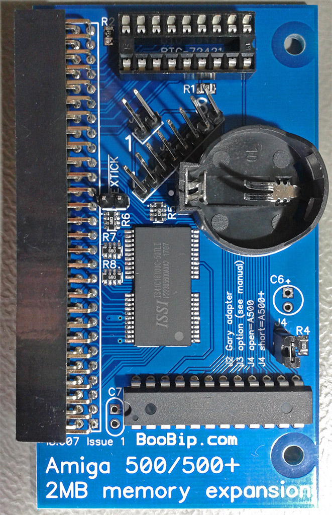
Memory board
Installed

Notch on Gary points RIGHT.
Pre-installation
If you need to upgrade your Kickstart ROM then do this first. Check the Amiga powers up and works correctly with the new Kickstart ROM.
If you choose to install the RTC chip and battery for an Amiga 500 then ensure the notch on the chip lines up with the socket. The notch should point RIGHT & away from the expansion connector.
If you have a revision 3 Amiga 500 then you must modify the memory board. Fit a 47pF ceramic capacitor in position C7 and cut labelled PCB track on the underside. If you ask before ordering I can send you a board pre-configured for a revision 3 Amiga 500.
Memory board installation
- Configure the jumper links on the memory board depending on your Amiga model
J4 EXTICK A500 open short A500+ short open - Carefully open the trapdoor panel. The plastic is 30+ years old and can be damaged or cracked.
- Line up the memory board with the expansion connector in the Amiga. It only goes one way round - with the bottom of the board (pin side) visible from the bottom of the computer.
- Gently push the memory board to mate the expansion connectors. The pins will slide into the connector by 8mm (1/4").
- Refit the trapdoor cover.
Gary adapter installation
Fit and test the memory board on its own before fitting the Gary adapter.
Warning: Only attempt the chip RAM mod if you have the correct tools and are confident in soldering your Amiga.
You only need the Gary adapter on an A500+ if you intend to do the chip RAM mod - not recommended for beginners.
Warning: Battery corrosion on an A500+ often reaches the Gary socket. A corroded socket may break when trying to remove Gary. If your board has corrosion then you might need to replace the Gary socket on the motherboard. Not easy for a beginner.
The Amiga community is large and very helpful :) - check the forums for info, help and recommendations for modification/repair services.
- Carefully open your Amiga 500/500+ case. There are 3 screws at the front and 3 screws along the back.
- Lift the lid. There are clips on the left and right side of the case holding the lid down. Be patient and gentle, the plastic is 30+ years old and the clips can easily be snapped. The design is frustrating and I find the lids a pain to remove! A spudger tool or flat screwdriver can help.
- Remove the keyboard and upper RF metal shield.
- Locate Gary - the right most 48 pin chip on the motherboard.
- Carefully remove Gary to avoid bending any pins.
- Insert the Gary adapter in the empty socket with the header pointing towards the front.
- Carefully insert Gary into the socket on the adapter. The notch should point towards the right.
- Double check Gary orientation and for bent pins.
- Connect the 8 pin cable between the the Gary adapter and the memory module. Pin 1 is BROWN on the cable. Pin 1 is marked on both PCBs with a "1". The cable should neatly fit through the gap in the top and bottom RF shields.
- Test the machine before attempting the chip RAM mod if you are going to.
- Optional: chip RAM mod - see separate sheet for A500/A500+
- Refit the RF shield, keyboard and top case.
Chip RAM mod
See dedicated page or A500 chip RAM modification.
See dedicated page for A500+ chip RAM modification.
Testing
If everything has gone well you should be greeted with a normal Kickstart screen on power up.
If your computer does not start double check all the connections and the A500/A500+ jumper is correctly set for your machine. For factory standard Amiga 500 EXTICK jumper should be fitted.
- Load Workbench.
- Check the memory shown at the top of the screen.
- Open Shell from the Workbench disk.
- Run "avail" to list your memory.
- Try a program/game/demo that requires extra memory - e.g. The Fall by Deadliners & Lemon (deadliners.net)
Keir Fraser's SysTest (https://github.com/keirf/Amiga-Stuff) has a memory test. SysTest will detect the expansion memory and test it.
John Hertell's DiagRom (http://www.diagrom.com/) is also a useful tool.