32kB ROM/RAM Installation
Important
Static electricity
The module can be destroyed by static electricity. Care should be taken to ground yourself before touching the module or any circuitry in the BBC. Older 74 series logic can be fairly robust to static discharge but CMOS and modern surface mount components are susceptible.
Basic static precautions are simple and free!
Plug in the BBC's mains plug but keep it switched off at the outlet. Then touch the bare metal of the power supply or UHF modulator with a finger. Easy!
Correct orientation
The module can be destroyed by incorrect insertion. Be careful when inserting the module that the pins are aligned correctly and the orientation is correct. Incorrectly inserted/orientated modules may be destroyed and cause damage to your BBC. Likewise, incorrectly inserted paged ROM in the piggy back socket may damage the ROM.
Be careful to double check the alignment and orientation when installing upgrades and paged ROMs.
Photos
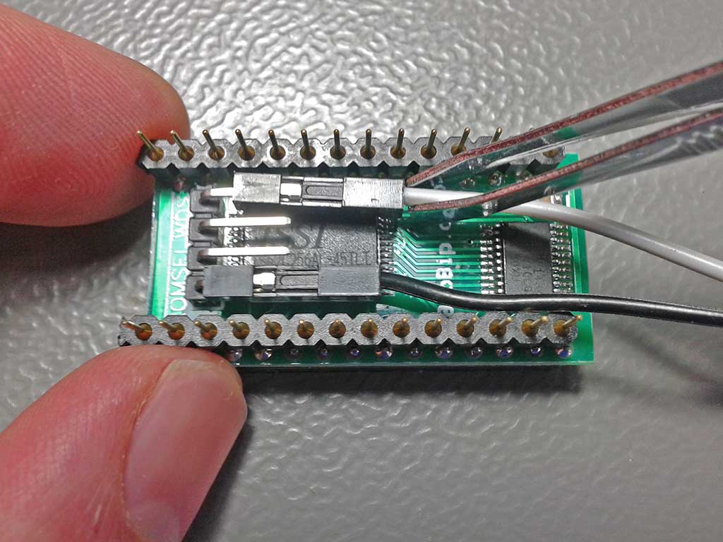
Wires
Installed
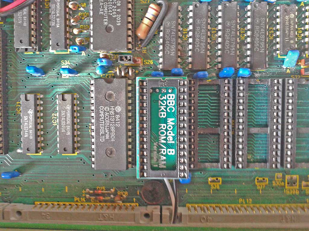
Notch on socket towards back of the BBC and wires exit towards the front.
Clips

Installation
Tools needed are a Philips No.2 screw driver to open the case. A Philips or flathead screwdriver (depending on your exact BBC) and a spanner/socket or pliers to remove the keyboard. Tweezers or fine needle nose pliers.
- Open the BBC case. Two (large) crosshead screws underneath at the front and two at the back. The lid then hinges up and off at the back.
- Remove the bolts holding in the keyboard.
- Lift and pull the keyboard forward to expose the ROM sockets (front right). You do not need to disconnect the keyboard wire but may if you want better access.
- Connect one long clip wire to the left most pin labelled ROMSEL. Connect the second long clip wire to the right most pin labelled WDS. Note which colour wire you connected to which signal. Tweezers make it easy to push the connectors on to the header.
- Insert the module in a free ROM socket. The central orientation notch in the piggy back ROM socket should be towards to the back of the BBC. The wires should come out underneath towards the keyboard. (You should not need much force to push the module into the socket - check the pin alignment if it doesn't go in easily.)
- Optional - install a ROM in the piggy back socket.
- Connect the ROMSEL spring clip to IC26 (left of the CPU) pin 5. (Pin 1 is top left count anticlockwise). See photo.
- Connect the WDS spring clip to IC73 (under analogue port) pin 24. (Pin 28 is top right count clockwise). See photo.
- Bolt keyboard back in and close case.
Accidentally connecting the spring clips to the wrong pins will not cause harm to the module. If the spring clips are disconnected then the RAM will not work and only the high ROM image will be visible but the BBC may well boot. Check that the spring clips do not short circuit to the adjacent pins.
Short jumper wires are provided to connect WDS and ROMSEL between multiple modules.
Advanced
If installing multiple modules connect the central ROMSEL and WDS headers to the 2nd board with the short jumper wires provided.
If IC26 or IC73 are inconvenient then alternate pins for the clips can be used.
ROMSEL
- IC26 pin 5 (74LS139 left of 6502 CPU)
- IC76 pin 9 (74LS163 under keyboard ribbon cable)
WDS
- IC73 pin 24 (uPD7002 next to analogue port)
- IC77 pin 8 (74LS00 near the copyright logo where it says the issue number)
- IC78 pin 10 (8271 above keyboard connector)