EPROM Emulator Installation Guide
Installation
Warnings
- Electronics can be destroyed by static discharge
- Do not hotplug using 0.1" USB headers!
- Do not insert module backwards!
- Do not insert module incorrectly in 42 pin socket! (e.g. Commodore A500+)
Double check orientation of the module before turning on the power. Incorrect installation may cause damage to your module and puts your hardware at risk. Pin 1 is the square pin marked with 1 on the silkscreen.
The modules are static sensitive. Take basic ESD precautions: ground yourself before handling the module by touching exposed shield, earthed metal, radiator etc. Use a ESD wrist strap if you have one.
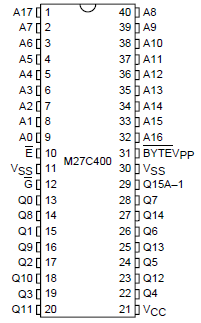
Pinout
Pin 1 is the square pin at the opposite end from the USB header.

Pinout Jumper
The /JEDEC solder jumper changes the pinout to support older Commodore Amiga ROM pinout. This was used on Revision 3 and Revision 5 Commodore A500. I
| Jumper | Pinout option |
|---|---|
| OPEN | JEDEC (27C400) |
| SHORT | Commodore A500 rev 3 / rev 5 |
USB connection
1. Permanent
Solder headers, adapter or wires directly to the USB header on the module.
e.g.

2. Temporary
Programming only takes a few seconds & can be done without soldering. Build an adapter as shown below and use a standard USB micro cable.
Warning! Do not hot plug USING 0.1" USB headers!
Make header connection then plug USB connector into PC/Mac.
- Insert pins into holes on module & hold with slight pressure
- Insert USB plug into PC/Mac
- Connect & program
- Remove USB plug from PC/Mac
- Remove pins from header

Basic installation
40 Pin socket
Pin 1 on the module is maked with a "1" on the silkscreen and has the square pin. Ensure pin 1 lines up with the notch on the socket.
e.g. Commodore Amiga 500

42 pin socket
When using 27C400 configuration in a 42 pin socket (e.g. Commodore A500+ or A1200) the empty row must be at the notch end of the socket. There are markings on the Commodore motherboards to show where a 40 pin chip must be inserted.
e.g. Commodore Amiga A500+

Incorrect insertion will damage the modules! One pin out and you connect +5v to GND and will cause damage. Original kickstart ROMs will be destroyed in the same way.
e.g. Commodore A500+


32 bit Installation
For 32 bit machines you need two modules. To guarantee they switch in sync the modules should be linked with wires.
| Mode | Link |
|---|---|
| 27C400 (512KB) | A18-A18 and A19-A19 |
| 27C800 (1MB) | A19-A19 |
Use preset wizard (options menu) to configure one module as MASTER and other as SLAVE.
The slave module will use the bank selection signals generated by the master.
e.g. Modules linked for Commodore A1200 use

27C800 (1MB) / 27C160 (2MB) Instalation
27C800 (1MB) and 27C160 (2MB) are 42 pin chips. They have an extra row of pins at the top of the chip.

A18 and A19 are available on pads at the top of the emulator.
- Cut 21 pin strip
- Solder with spare pin above pin 1 and pin 40
- Solder wire from A18 pad to new pin 1
- Solder wire form A19 pad to new pin 42
